
Story so Far: See Story so Far and TL;DR sections of Part 1.
TL;DR: My circuit needs another resistor or it will continue frying everything. It claimed another few victims before I realised this though.
After the traumatic experience it had endured I decided to give the laptop a break for a while and instead maybe check up on my circuit wiring. We were well into the evening now and the garage was engulfed by the umbra of the garden hedges, but I had been using the head torch all day, so had to switch it to the dimmer mode to save energy. The dimmer works exactly how I described dimming LEDs in “The Impossible Dim” except badly done whereby the flicker is pretty noticeable, giving a slight stroboscopic effect. It was annoying, but still better than being stuck in the dark before I finished. I rewired my circuit and gave it juice, same problem as in part 1, light comes on but just stays at full brightness. I had pretty much exhausted my troubleshooting list at this point, so I let the lamp stay on and willed the problem to make itself known. The “warm” white lamp really gave a much more homely feel to the workstation than the migraine inducing “Transfiguration of Christ brilliant” white headtorch LEDs.
The cooker hood bulbs being used in the lamp meant it gave off that special hue of light that is enriched with nostalgia. Nostalgia for all those nights having went straight to hurling training after school and arriving home battered, bruised and seeking comfort. Finding it wrapped in foil on the stove top. A home-made dinner that had watched on while everyone else enjoyed their meal and discussed their day; during post-dinner clean-up it was lovingly wrapped up in foil so as to capture a healthy serving of the Family Table spirit under there with it. Then as I land home, I am welcomed by the working-class cloche basking in the warm glow of the cooker hood bulb; a glittering, scintillating treasure trove. I approach the light through the darkened kitchen, with each step forward my shoulders bob up and shrug off more of the day’s tension, and with each breath inward the scents of the kitchen build hope for what might be waiting. I reach the stove. Quick breath in. Hold it. Lift the foil . . . pork chops. Stuff that I’ll have porridge.
Yep, the light being given off by the bulbs was lovely, but I wasn’t so keen on the smell – the smell?! . . . suddenly the illusion of homeliness came crashing down as the scent of melting plastic made itself known. I glanced down to the workbench and the strobe of the headtorch made the pixie smoke1 cast a large, jittery shadow, giving the illusion of a much larger plume of smoke billowing out than there was. I’ll blame the ensuing overreaction on that.
I immediately switched the supply off and for absolutely no rational reason whatsoever began ripping my circuit apart. I believe I believed I was protecting the components from being harmed by the now disconnected and harmless power supply. All very silly behaviour. The only component really in use was the FET (the “dimmer switch” that the Arduino was supposed to be controlling). Now, there’s a couple of conditions where a FET will get very hot inside and try to get rid of that heat through its back panel; I had created one such condition2. To get rid of dangerous levels of heat the small back panel of a FET often requires a larger heatsink3 stuck on to it, I didn’t have such a tool attached, that is, until I tried to grab the FET and disconnect it. At that moment, my hand became the additional heatsink and the FET did its utmost to utilise it, sending whatever heat it could into my fingers. Very painful. Very very stupid. Very very very educational.
So, in summary, things fried in an attempt to build the simplest part of this alarm clock:
- Laptop’s USB port
- FET
- My fingers
- My brain
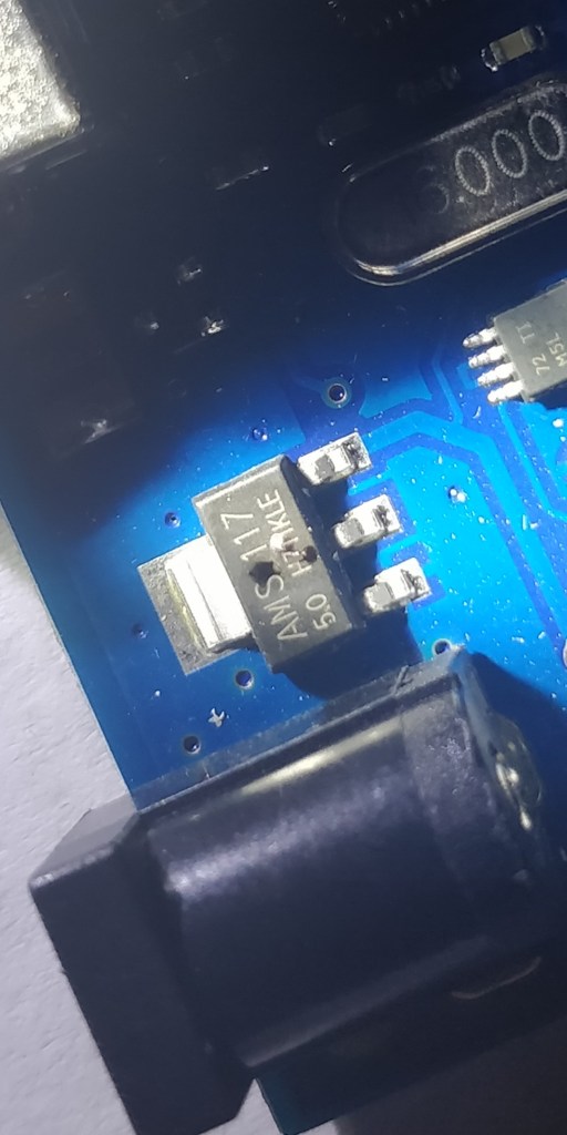
- Voltage regulator chip on the Arduino
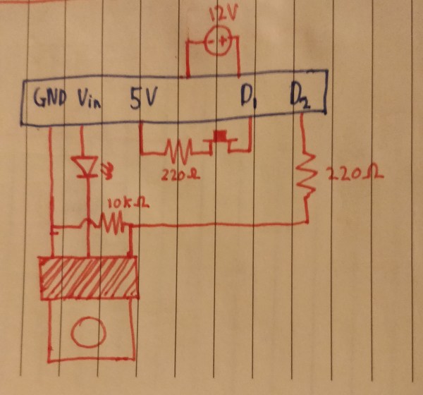
The last of which was what had actually been producing the pixie smoke earlier. It takes the 12-Volts from the supply and steps it down to 5-Volts for the bits that like to work at 5-Volts. The only one of which I was using at the time is the pin controlling the FET. I had pretty much shorted said pin to the ground which meant it was trying to draw Unlimited Power (infinite current more specifically but Star Wars). That power was (obviously) too much for the wires in the voltage regulator to carry so they started trying to get rid of it by heating up their plastic casing. Which melted.
The fix is very simple; add a resistor to the wire. All this is like dropping a watermelon off a 45-metre tower. As it falls it will get faster and faster, creating self-destructive carnage when it lands. Adding the resistor is like giving the melon a parachute, it limits the amount of speed the melon can gather on its way down to the point where you can drop it all day and not see red.
My short-sighted shorting had one more side effect; it had actually caused a failure inside the FET which meant it no longer operated as a dimmer switch and instead had become just a lump of metal, or a dimmer switch stuck at its maximum brightness4 hence the issues I was having. I suspect things got quite hot inside the FET and some tiny bits melted together, only to be cooled down by passing their heat off to my fingers.
After making sense of everything I ordered a new Arduino and repeated the experiment, now incorporating an appropriate resistor and new FET, the lamp works perfectly, dimming and brightening at will.
Incidentally, I referred to the Arduino as an “Uno board” in early blog posts, said posts were written before this Series of Unfortunate Events, at a time when I was using the Oosoyoo Uno (a knock-off of the Arduino Uno) which now, as you know, has a burnt-out voltage regulator. After the events detailed above, I figured I’d like to splash out on the real deal Arduino model. Started From The Bottom Now We’re Here.
1 – See previous post “Mouth Function Malfunction” for etymology of “pixie smoke”. Suffice to say it’s a quirky term for smoke from electronics.
2 – FET == MOSFET for the sake of this blog. My FET wasn’t for microcontrollers – the gate voltage should have been much higher than 5V to fully turn it on. Since I was only giving it 5V it was only partially turned on and still had quite a large resistance. Thus it was a resistive heating element, melting itself and giving off heat. It is now switched out for a “logic level” FET. 5V turns it on all the way – assuming my pwm frequency isn’t ridiculously high, apparently this can lead to the gate not having time to fully activate every cycle.
3 – A heatsink is just a block of metal that absorbs heat from a component faster than the air around that component can. It then has a large surface area in contact with the air to pass that heat on to the environment effectively. It then keeps on wicking heat away from the component. The more surface area exposed to air it has the better at its job a heat sink is – this is why they almost always have a finned design.
4 – I know that’s not quite right as the FET isn’t a dimmer switch in the classical sense (a potentiometer) but it’s accurate enough. More accurately the FET became just another bit of wire in a circuit with a 12V source (wall wart) and a 5V source (digital pin) powering 2 LEDs.


