Story so Far: See Story so Far and TL;DR sections of Part 1.
TL;DR: My circuit needs another resistor or it will continue frying everything. It claimed another few victims before I realised this though.
After the traumatic experience it had endured I decided to give the laptop a break for a while and instead maybe check up on my circuit wiring. We were well into the evening now and the garage was engulfed by the umbra of the garden hedges, but I had been using the head torch all day, so had to switch it to the dimmer mode to save energy. The dimmer works exactly how I described dimming LEDs in “The Impossible Dim” except badly done whereby the flicker is pretty noticeable, giving a slight stroboscopic effect. It was annoying, but still better than being stuck in the dark before I finished. I rewired my circuit and gave it juice, same problem as in part 1, light comes on but just stays at full brightness. I had pretty much exhausted my troubleshooting list at this point, so I let the lamp stay on and willed the problem to make itself known. The “warm” white lamp really gave a much more homely feel to the workstation than the migraine inducing “Transfiguration of Christ brilliant” white headtorch LEDs.
The cooker hood bulbs being used in the lamp meant it gave off that special hue of light that is enriched with nostalgia. Nostalgia for all those nights having went straight to hurling training after school and arriving home battered, bruised and seeking comfort. Finding it wrapped in foil on the stove top. A home-made dinner that had watched on while everyone else enjoyed their meal and discussed their day; during post-dinner clean-up it was lovingly wrapped up in foil so as to capture a healthy serving of the Family Table spirit under there with it. Then as I land home, I am welcomed by the working-class cloche basking in the warm glow of the cooker hood bulb; a glittering, scintillating treasure trove. I approach the light through the darkened kitchen, with each step forward my shoulders bob up and shrug off more of the day’s tension, and with each breath inward the scents of the kitchen build hope for what might be waiting. I reach the stove. Quick breath in. Hold it. Lift the foil . . . pork chops. Stuff that I’ll have porridge.
Yep, the light being given off by the bulbs was lovely, but I wasn’t so keen on the smell – the smell?! . . . suddenly the illusion of homeliness came crashing down as the scent of melting plastic made itself known. I glanced down to the workbench and the strobe of the headtorch made the pixie smoke1 cast a large, jittery shadow, giving the illusion of a much larger plume of smoke billowing out than there was. I’ll blame the ensuing overreaction on that.
I immediately switched the supply off and for absolutely no rational reason whatsoever began ripping my circuit apart. I believe I believed I was protecting the components from being harmed by the now disconnectedand harmless power supply. All very silly behaviour. The only component really in use was the FET (the “dimmer switch” that the Arduino was supposed to be controlling). Now, there’s a couple of conditions where a FET will get very hot inside and try to get rid of that heat through its back panel; I had created one such condition2. To get rid of dangerous levels of heat the small back panel of a FET often requires a larger heatsink3 stuck on to it, I didn’t have such a tool attached, that is, until I tried to grab the FET and disconnect it. At that moment, my hand became the additional heatsink and the FET did its utmost to utilise it, sending whatever heat it could into my fingers. Very painful. Very very stupid. Very very very educational. So, in summary, things fried in an attempt to build the simplest part of this alarm clock:
Laptop’s USB port
FET
My fingers
My brain
Voltage regulator chip on the Arduino
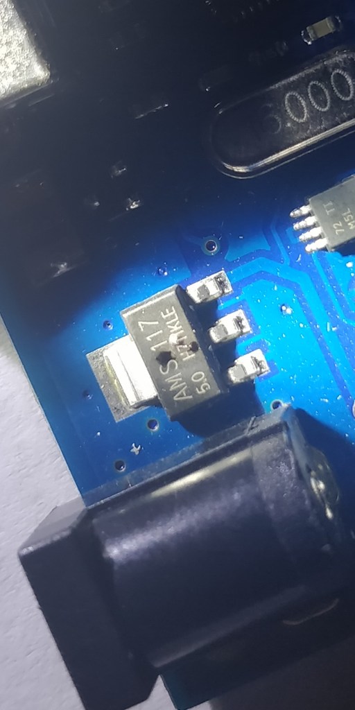
The last of which was what had actually been producing the pixie smoke earlier. It takes the 12-Volts from the supply and steps it down to 5-Volts for the bits that like to work at 5-Volts. The only one of which I was using at the time is the pin controlling the FET. I had pretty much shorted said pin to the ground which meant it was trying to draw Unlimited Power (infinite currentmore specifically but Star Wars). That power was (obviously) too much for the wires in the voltage regulator to carry so they started trying to get rid of it by heating up their plastic casing. Which melted.
Slick patches on “AMS 117” chip are the bits that melted especially well.
The fix is very simple; add a resistor to the wire. All this is like dropping a watermelon off a 45-metre tower. As it falls it will get faster and faster, creating self-destructive carnage when it lands. Adding the resistor is like giving the melon a parachute, it limits the amount of speed the melon can gather on its way down to the point where you can drop it all day and not see red.
My short-sighted shorting had one more side effect; it had actually caused a failure inside the FET which meant it no longer operated as a dimmer switch and instead had become just a lump of metal, or a dimmer switch stuck at its maximum brightness4 hence the issues I was having. I suspect things got quite hot inside the FET and some tiny bits melted together, only to be cooled down by passing their heat off to my fingers.
After making sense of everything I ordered a new Arduino and repeated the experiment, now incorporating an appropriate resistor and new FET, the lamp works perfectly, dimming and brightening at will. Incidentally, I referred to the Arduino as an “Uno board” in early blog posts, said posts were written before this Series of Unfortunate Events, at a time when I was using the Oosoyoo Uno (a knock-off of the Arduino Uno) which now, as you know, has a burnt-out voltage regulator. After the events detailed above, I figured I’d like to splash out on the real deal Arduino model. Started From The Bottom Now We’re Here.
1 – See previous post “Mouth Function Malfunction” for etymology of “pixie smoke”. Suffice to say it’s a quirky term for smoke from electronics.
2 – FET == MOSFET for the sake of this blog. My FET wasn’t for microcontrollers – the gate voltage should have been much higher than 5V to fully turn it on. Since I was only giving it 5V it was only partially turned on and still had quite a large resistance. Thus it was a resistive heating element, melting itself and giving off heat. It is now switched out for a “logic level” FET. 5V turns it on all the way – assuming my pwm frequency isn’t ridiculously high, apparently this can lead to the gate not having time to fully activate every cycle.
3 – A heatsink is just a block of metal that absorbs heat from a component faster than the air around that component can. It then has a large surface area in contact with the air to pass that heat on to the environment effectively. It then keeps on wicking heat away from the component. The more surface area exposed to air it has the better at its job a heat sink is – this is why they almost always have a finned design.
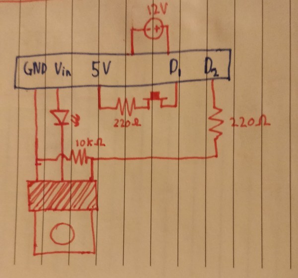
4 – I know that’s not quite right as the FET isn’t a dimmer switch in the classical sense (a potentiometer) but it’s accurate enough. More accurately the FET became just another bit of wire in a circuit with a 12V source (wall wart) and a 5V source (digital pin) powering 2 LEDs.
Just a reminder this is what the end circuit will now look like. Except the pins aren’t accurately labeled and there’s a grounding wire omitted. I think the omitted wire is superfluous anyway though.
TL;DR: Rounding out the parts list; stripboard to solder everything onto, switches for safety features and controlling the lamp, a capacitive sensor to wake the clock screen and MOSFETs to control the currents that the Arduino can’t directly. Electricity is dangerous.
This isn’t the most universally entertaining post, it’s quite technical. The next post will be more creative talking about the blog itself and going momentarily off the narrative of building the clock. For this post there’s levity injected where possible but that’s not so regular, as you can assume by this disclaimer: I don’t recommend trying this project. This is not an instruction manual or reference material for electrical work, I am a very inexperienced engineer writing (believe it or not) with the intention of being entertaining, at least to myself. Assume everything I write – especially about health and safety – to be completely subjective and even more-so completely incomplete. For example, I conclude 12V is probably harmless; that means 12V DC, through my skin, while dry, at room temperature and for less than a few seconds. All of that is far too mundane to include in a blog that is already fighting against by abilities as a writer (or lack thereof) to be entertaining. Stay alive. For the uninitiated, the footnote* (foot-essay) might be worth reading first – only the first bit about why wires might get hot though.
The basic parts list is now done; cartridge heater, LEDs, copper wire, clock, LCD. However, there’s a few more bits to add, mostly as a result of working with the fairly substantial 60W power supply. Given the supply provides 12V, my highly resistive skin should provide me with all the protection I need to avoid electricity induced burns or muscle contractions. While my skin is highly resistive, all sorts of things effect that, wet skin that has had a potential difference held across it for a long time (e.g. if I’ve just come back from the bathroom and am absent-mindedly holding wires while I try to regain my bearings) can start to accept a lot more current than it ought to. Essentially, electricity preys on fear; every bead of sweat that coats your hand makes it easier for the energy in one wire to make its way to the other by forming a path of destruction through your skin, nerves and muscles. Every second you hesitate, it breaks down your skins defences, bending your body to its will until your natural defences are overcome. Electricity pursues its mission to go from high potential to low potential with the type of tenacity and ruthlessness that extreme capitalist culture encourages people with a lack of empathy to pursue the opposite path – from low to high potential. As far as electricity is concerned the only difference between a path and a roadblock is time.
Lightning isn’t so much just a matter of time as the potential difference between the clouds and ground is actually getting higher. However, if there was a somehow lightning bolt shaped path of especially humid air, it’s definitely more likely to see a strike, similar to wet hands – more water means lower resistance (in these cases). Pretty similar concept to when things short circuit if you spill water on them too. Photo by luiisrtz on Pexels.com
Still, substantial current through me is unlikely, but if I drop a screwdriver which lands on some wires, current might flow through it and it can quite quickly get hot enough to burn me as I try to pick it up, then I’ll recoil as if in fear of this possessed screwdriver pursuing a further attack. It’s that recoiling that can lead to me hitting my head on the table or slamming my hand on a drill bit or something hot. I know that sounds like the conjecture of an overprotective mother but you learn very quickly working with electricity that these fears are well-founded. The tidiest workshops you’ll see are those concerned with electrical equipment, the electricity supply in such workshops (not in your house or garage) is fairly safe with so much in the way of safety switches and fuses but it will still shock you. Its your knee jerk reaction that’s dangerous – a quickly retracted arm is a prime target for the exposed blade left lying around after stripping wires. Or perhaps a flailing leg is the mechanism by which the acid, imprisoned in a testing jar against its will for too long, makes good its escape. These risks are very real and make one appreciate a tidy workspace. It is wise, then, for me to keep track of where things are and where they should be, but also to buy a few switches, allowing me to turn the supply off without unplugging it every time and, more importantly, without being close to the plug. I’ll just need to make sure I know very well which side of the switch I’m working on at all times. The switches will also find use in the end product, one to allow me to turn the light on and off like a normal lamp. Another as a sort of disconnector for the heating system as the heater says it’s comfortable operating at 350 degrees Celsius. That’s fine for the heater but everything around it, including me, would be very uncomfortable if it got anywhere near that. So I’ll need a kill switch to keep it in line in case the innate pyromaniacal tendencies ever take over. My main concern is the brains of the operation, the Arduino, coercing the heater into some sort of suicide pact while I’m not around, or teasing it, saying “I bet you can’t really get that hot”. So to prevent this I’ll put the heater into isolation from the rest of the circuit by flicking a switch as I pick up my morning cuppa and reconnect it when I set a new cup on at night. I agree; isolating the innocent, naïve party is the wrong approach entirely, the heater would never turn itself on if left unprovoked by the Arduino – the bad influence should be the one that suffers social isolation all day. Unfortunately though, reprimanding the Arduino will only lead to the rest of the students – I mean components – acting out. It’s the coward’s way out for sure but thankfully the heater doesn’t have the mental capacity to be instilled with trauma from this dreadful mistreatment. A mistreatment which only serves to accommodate the obviously emotionally incompetent and lazy teachers – I mean technically incompetent and lazy me – who can’t be bothered to work out an alternative. This of course wouldn’t be a bothersome thing to work out for a more competent engineer. So the real root of the problem clearly lies in the training processes completed by the people charged with the care of these children – I mean person charged with making this clock. If I was to detail the problem more literally – the Arduino might turn the heater on due to a bug in my code or an unplanned clock reset. If there’s no cup to heat, there’s no telling where that enormous amount of heat energy will get redirected to – my fingers, though, trembling with trepidation almost to the point of forgetting they’ve got a job to do in typing right now, seem to think that they’re a prime target for getting cooked.
I’ll use a stripboard to link all components together – not much to say about that, it’s just a lot of strips of copper on a board that I can solder things to, making a circuit. They come with good current ratings so I can avoid anything getting hot.
Switches are fine for most things but to wake the LCD screen and request it to display the time, I think a touch sensitive button would be pretty sleek. I have an old phone which pretty much every part of has perished and figured the onboard fingerprint sensor could do the job, so I set about taking the phone apart, brutally ripping off its already busted screen and leaving my bedroom floor looking like the 33rd floor of Nakatomi Plaza in the process. Heartbreakingly, the sensor had special connections that I couldn’t make use of. Which I most certainly could have just found out using Google. Thankfully touch sensors are fairly easy to make from pretty much any sheet of metal and a resistor. One of the heat sinks in the phone is a perfectly sized sheet of copper to make a button out of, so the John McClane cosplay wasn’t completely in vain.
A touch sensor (the blue wire and everything to the right of it). Quickly prototyped on a breadboard using a steel soldering iron rest as the “button”. The bigger the metal sheet used, the more sensitive the button is – in this case I could just hover my hand near it and still be sensed.
Lastly but probably most importantly, we need to return to that whole Arduino being a bit of a manipulative bully analogy from earlier to understand why I need MOSFETs – that’s an acronym, I’m not just super excited to talk about these special transistors, I am a little excited, though. During uni I’ve looked into pretty much every analogy to try and understand a transistor’s inner workings; the interesting ones don’t explain it well and the ones that explain it well aren’t interesting, so I’ll spare you any attempt at describing it. The outer workings are pretty intuitive though – basically, the heater draws just over 4 Amps while (hopefully) boiling water, but the Arduino is unwilling to give it any more than about a tenth of that for fear of morphing into a heater itself and everything getting a bit melty (noticing a theme?*). To get around this, the Arduino can delegate the supply of current to the heater to a MOSFET, which is more than capable of commanding 4 Amps, but not without explicit commands to do so. Whereas before the Arduino would have had to push with everything it had and more to get the heater to even think about doing its job, it can now simply wave its hand to the newly appointed and very obliging enforcer which will wrangle the heater into compliance. MOSFETs, and all transistors, are basically switches that machines can control. So the heater will have its own direct line to every bit of power that the Arduino has access to but the MOSFET controls whether that line is in use or not, and the Arduino decides what the MOSFET decides, and I decide what the Arduino decides, and . . . I also think I’ll use a MOSFET to control the LED, it’s not really necessary here – I could wire it differently but incorporating the switch that allows the use of the LED as a regular lamp outside of sunrise hours gets slightly more involved and MOSFETs come in packs of 10 anyway. Pretty much everything I’ve mentioned on this shopping list has had to be bought in a pack of at least two which should be great for experimenting. Other than that, a few wires, a roll of tape and some solder will be needed but as best as I can make out the shopping list is complete for now! I’m not sure if I’ll actually write about this but I’ll also buy a few smaller LEDs and a breadboard which can be great for verifying the code works without getting a 12V supply and 50W heater involved.
A simple circuit using a MOSFET – the silver thing with a hole in it. All this circuit did was turn the bulb on and off. The silver holed part is actually just a heat sink, the magic happens in the black casing,. The fact that these come with a means to get rid of heat quickly should confirm that these little things can wield some serious power.
* A note on electricity and heat: People often think live wires are thermally hot – they shouldn’t be. The wire getting hot means it is giving off power as heat – where is it getting that power? It’s stealing from the power you have tasked it with carrying to your phone’s battery. If a wire has a limited number of electrons, (the particles tasked with carrying electrical current) attempting to transfer large currents means the electrons are overworked and start making mistakes, bumping into each other and generally getting all hot and bothered. The more this happens the more they hit each other and the more temper(ature)s flare. So it’s very important to ensure your wire has enough electrons to carry the current you’re trying to send through it, otherwise they’ll waste so much of it bumping into one another that the majority of your power has been given off as heat before it gets the chance to reach whatever you were trying to power. Thankfully the solution is simple, just employ more electrons – use a thicker wire, split the current between two wires or use a better conductor (with more free electrons per unit volume). There’s other ways too. The wires in the Arduino can carry 2 Amps without getting hot, above this they heat up and start melting the plastic board they’re embedded in.
I suspect no-one will be reading at this point – I’m about to tackle why touching live wires burns, even if the wire itself isn’t (thermally) hot – “hot” can also mean live when dealing with electricity. Honestly it’s only worth reading if you’re really interested, I’m mainly writing to improve my own understanding of it, I’ll still try to make it readable but it will be devoid of figurative language. Again – this is incomplete and quite possibly inaccurate!! If you put current through something resistive it will dissipate heat power to the tune of I2R; the current through it squared, multiplied by its resistance. Clearly if you’re using a high current then you need a very low resistance to avoid too much heat being dissipated. Also, voltage is equal to the current multiplied by resistance (V=IR for the acquainted). Voltage is the thing to watch out for primarily – also called potential difference as it represents the electrical potential between two points. A 12V DC supply like I’m using will have 12V of electrical potential between the red and black wires, if I were to grab both with one hand and my skin had resistance of 100,000 ohms, the current would be 0.00012 Amps through my skin. So referring back to the previous formula, 0.000122 x 100,000 = 0.00144 Watts of heat is dissipated by my hand – that’s just over the power my Wi-Fi router antenna emits – and I can hold that all day without getting warm. The FCC makes sure of that. At higher voltages the heat dissipated bymy hand will increase, the wire isn’t getting hot, I am. The maths for working out where real burning would occur is maybe a little beyond me and honestly pretty pointless since there is always the danger of something other than my hand coming between both wires and getting hotter than my hand would, coupled with the danger of me touching that something. Also, at a certain point, skin starts to get broken down because of electrical potential across it, causing its resistance to drop and allowing more current to flow – trying to factor this in is pretty much pointless as there are too many variables that will change every time you work – “have I showered yet today?” and “what did I have for lunch?” Also important is that long before burning actually occurs, other dangers will get to me, our brain communicates using minute electrical signals and so our pain receptors are fantastic at detecting electrical current, so while I may not be burning, I will be feeling tremendous amounts of pain. Muscles also begin to be overwhelmed by electrical signals and start convulsing, particularly troublesome around the lungs and heart. Although, humans being the fantastic race we are have developed life-saving defibrillators based on this principal to kickstart the heart with a big current induced contraction. Also also important is that mains supply and a huge amount of what you are likely to encounter is AC, not DC, which is something I shan’t go into except to say that AC doesn’t find your skin’s resistance to be so much of an issue. Electricity is very dangerous. Taking advice from strangers on the internet is very dangerous. Inferring advice from an entertainment-driven blog is very dangerous. Inferring electricity-related advice from a stranger’s entertainment-driven blog on the internet is very very very dangerous.